Fiber-coupled laser diode : this tutorial provides an overview of the technical properties of fiber-coupled laser diodes. The various laser diode families such as DFB laser diodes or multi-emitter high power laser diodes are described in this tutorial.
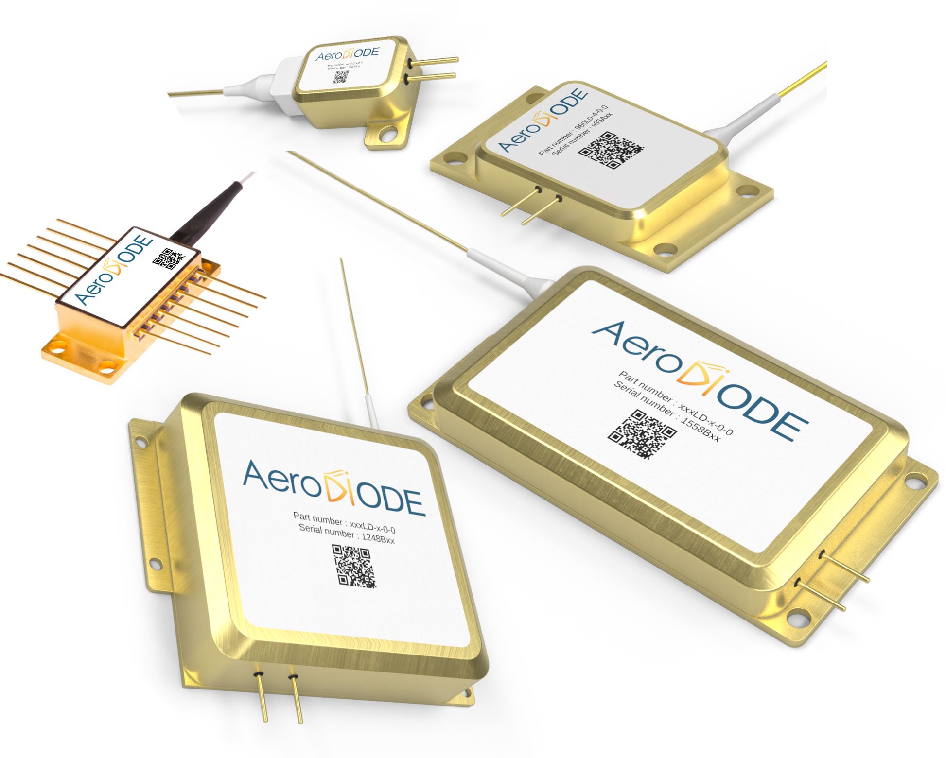
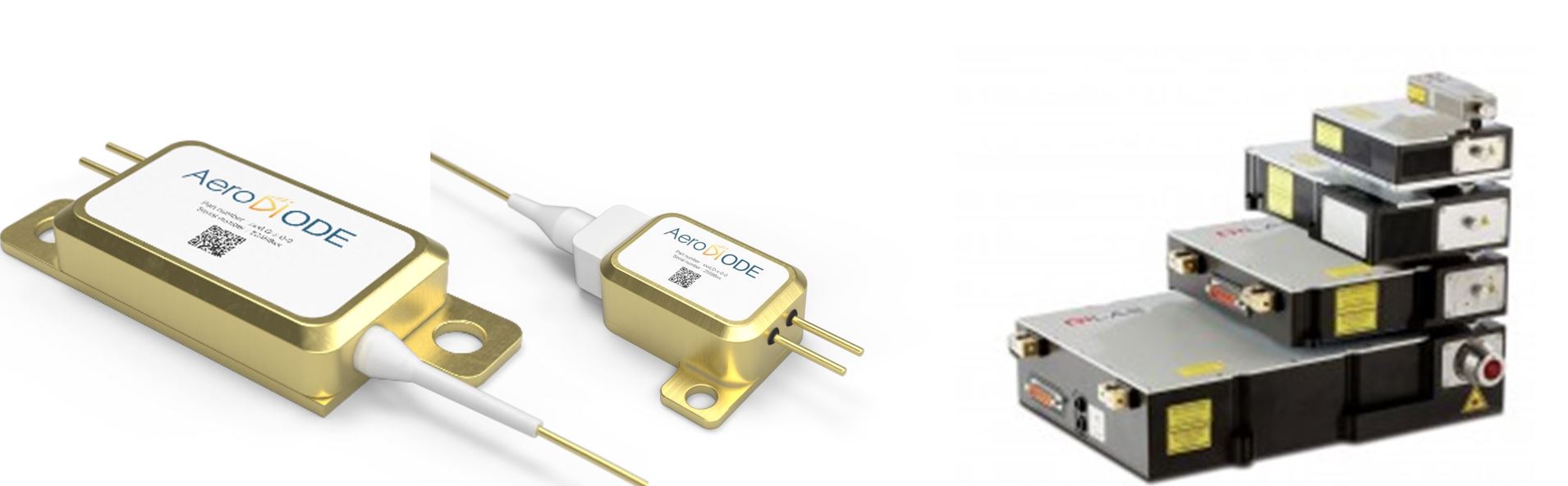
One singlemode and several multimode fiber coupled laser diodes from AeroDIODE
Introduction
Laser diodes are everywhere today. They are the simplest element to convert electrical power into laser power. Laser diodes are based on several semiconductor assembled materials (GaAs, InP or other more complex structures like GaN). Singlemode laser diodes are low power laser diodes (typically <1W) whereas multimode laser diodes are much higher power devices (typically >10 W up to several kW).
Optical fibers
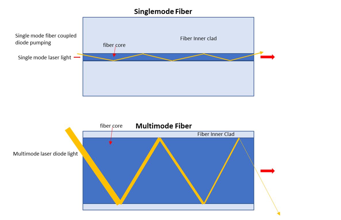
It is important to know the two types of active fibers that are commonly used to couple the light coming in from a laser diode:
Single mode fibers have a core of typically a few µm (for example ~6 µm around a wavelength of 1 µm, and 9 µm around a wavelength of 1.5 µm)
Multimode fibers are larger diameter fibers that can handle a much higher level of optical power. Standard versions have typically 62, 100, 200, 400, 800, or even > 1000 µm core diameter. The smaller the diameter, the easier it is to focus to a small spot the light coming from the fiber with a lens or a microscope objective.
Figure 1: Principle of a single mode or multi-mode fiber. The fiber core is much larger when considering a multimode fiber.
Polarization Maintaining fibers: Singlemode laser diode can be either standard (SMF) or Polarization maintaining (PM). In the latter, the optical fiber has a special clad structure which allows the maintenance of the polarization of light all along the fiber length.
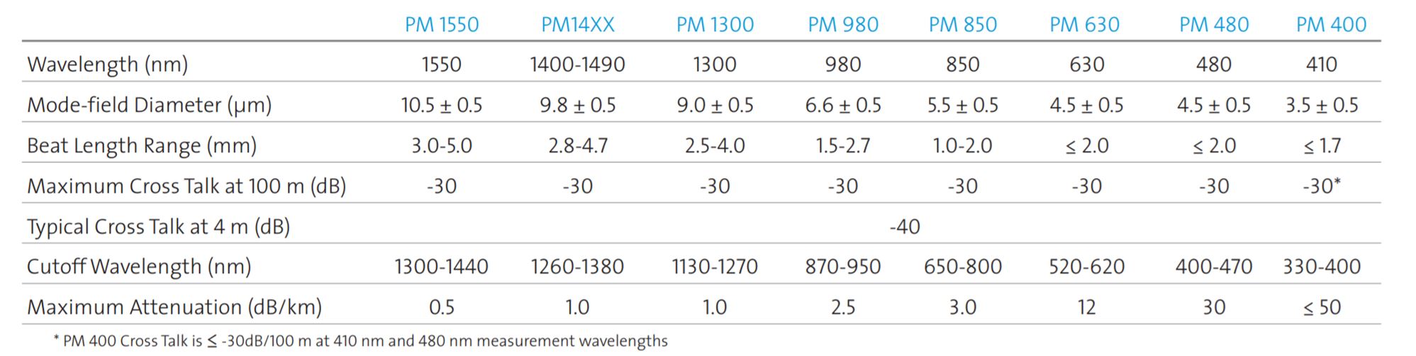
The table below shows the characteristics of various models of singlemode PM fibers offered by Corning Inc. One can see that the core diameter is getting very small as the wavelength decreases. An interesting data point to pay attention to in the table is the cutoff wavelength. A single mode fiber works fine when considering the wavelength between its cutoff wavelength and ~1.5 times this cutoff wavelength. Below this range the fiber becomes multimode, above this range the light can easily leave the fiber when bending it.
Figure 2 : Example of singlemode (PM) fiber characteristics offered by Corning Inc (Courtesy of Corning Inc – online datasheet)
Single mode fiber-coupled laser diodes
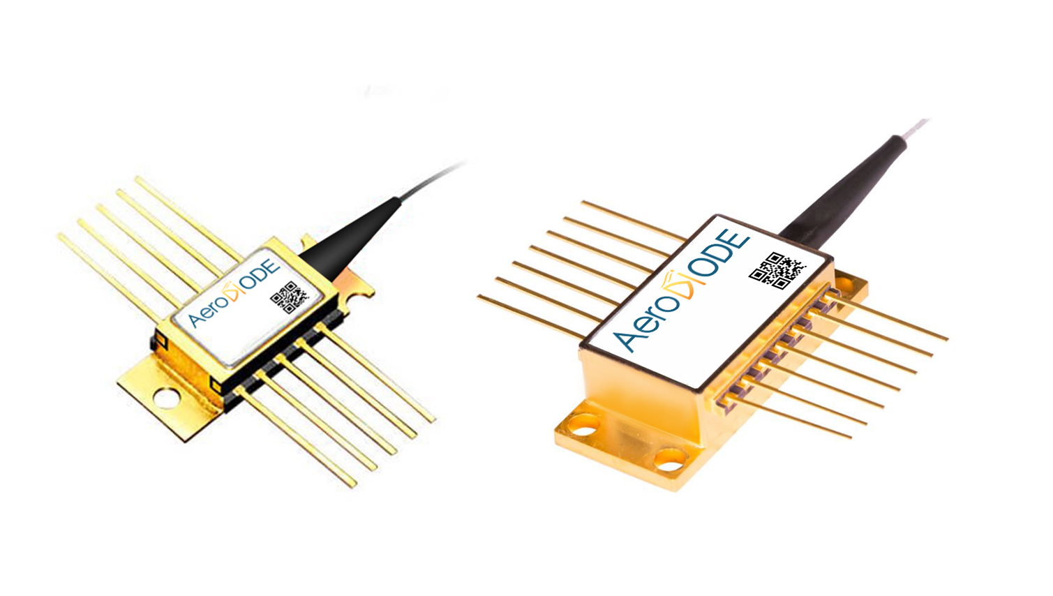
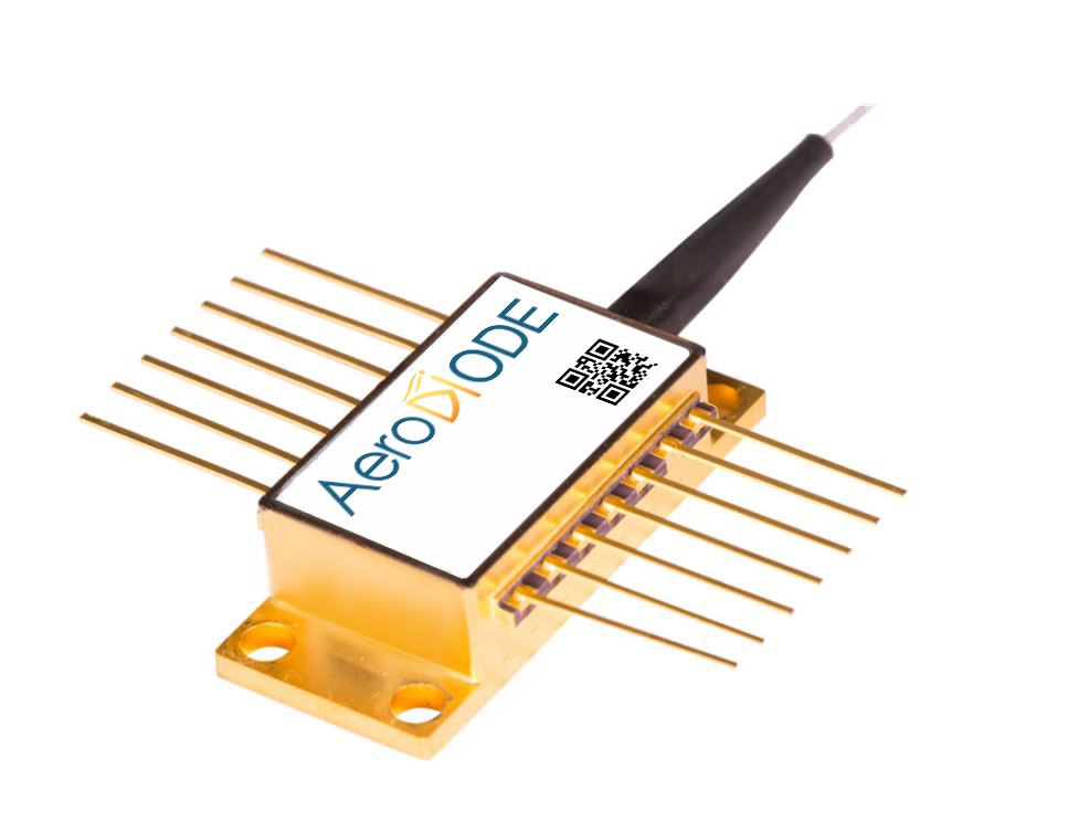
This type of laser diode is generally assembled in a package called “Butterfly” with a TEC cooler and a thermistor integrated into the package (the trend today being towards smaller form factors). A single-mode fiber-coupled laser diode is generally able to reach a few 100s of mW up to 1.5 W of output power.
Note that a butterfly package fiber-coupled laser diode is a complex device with many different possible pin configurations and several types of grounding configurations (Fully floating, anode grounded etc.). Assembling a butterfly package on a given driver requires some verifications.
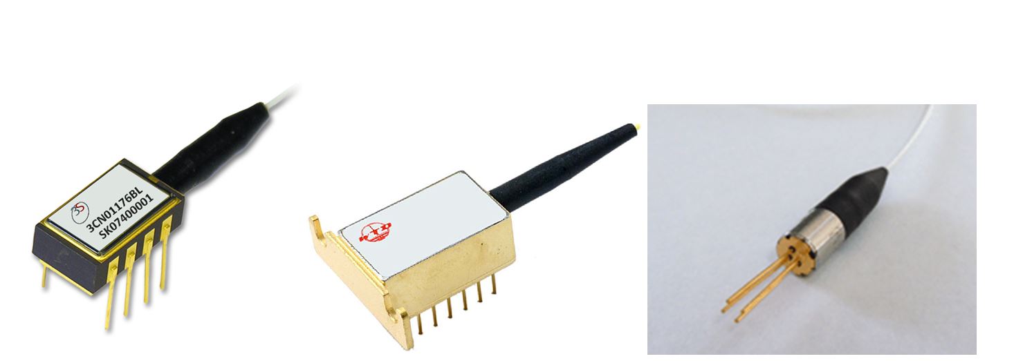
Figure 3 : Example of a single mode fiber coupled butterfly package laser diode emitting at 976nm (10 pin mini-butterfly (left) and 14 pin standard butterfly (right)). These laser diode modules include a TE-Cooler, a thermistor, and a Back-Facet Monitor (BFM) to measure the level of optical power.
Several other package form factors are available on the market. For example, the following DIL packages often met in the Telecom market or coaxial packages for typically <10mW power:
Figure 4 : Other types of fiber coupled laser diode form factors (mini-DIL (left), 14-pin DIL (middle) and coaxial (right))
The tendency today for the laser diode manufacturers in the low power Telecom or LIDAR market is to develop new coaxial packages with very small form factors but still including TEC, thermistor and BFM :
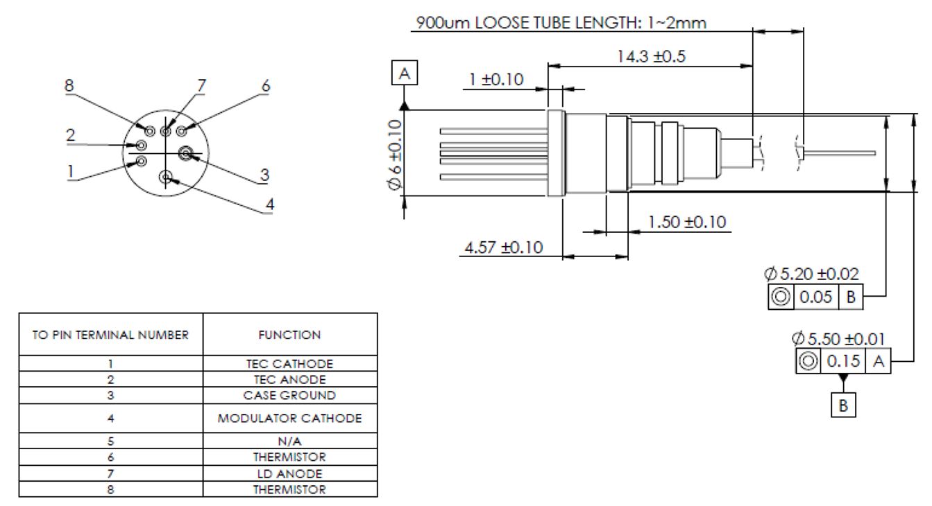
Figure 5 : Example of an impressive TOSA package which includes a laser diode, a TEC and a thermistor in a 6*5 mm package.
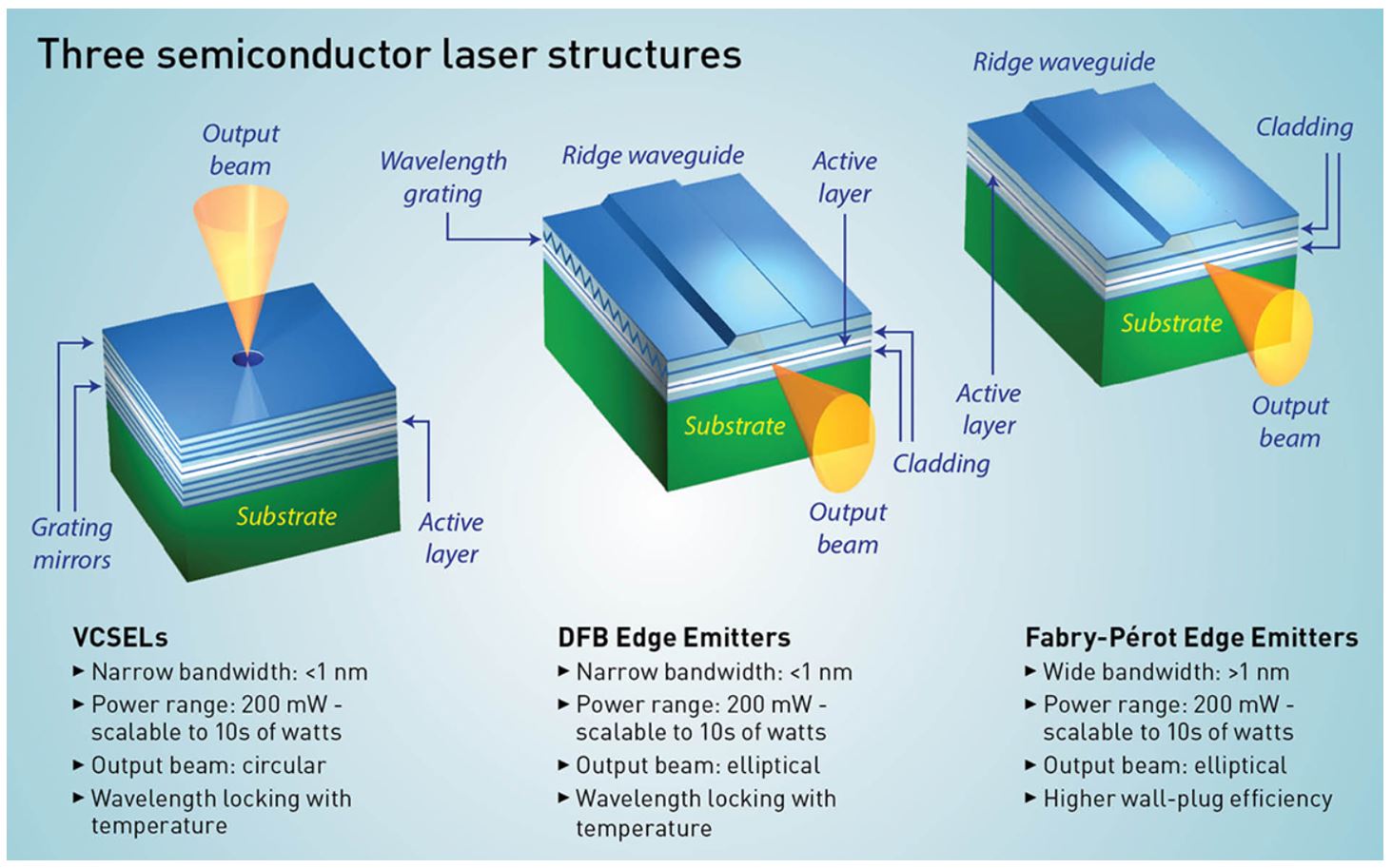
The figure below shows the 3 families of laser diodes generally seen on the market. VCSEL laser diodes are generally not fiber coupled. They are the types of laser diodes seen in large diffusion sensing applications such as computer mouse devices or smartphones 3D sensing face recognition.
DFB and Fabry-Perrot edge emitters, that are often fiber-coupled, are described below :
Figure 6 : 3 types of laser diodes emitters generally seen in the industry. (Courtesy of Phil Saunders/Optics and Photonics News)
a) Fabry Perrot laser diodes with or without Bragg grating
A “standard” fiber-coupled laser diode is a common partially reflecting semiconductor cavity where the back facet has a high reflective coating and the front facet a partially reflective one. Typical laser diode chip size is ~1*0.5*0.2mm.
The major typical characteristics are as follows:
Power ranges can reach >1.5 W for singlemode (and much more for multimode versions, see below)
The bandwidth is generally broad (>1nm)
The output beam is strongly elliptical.
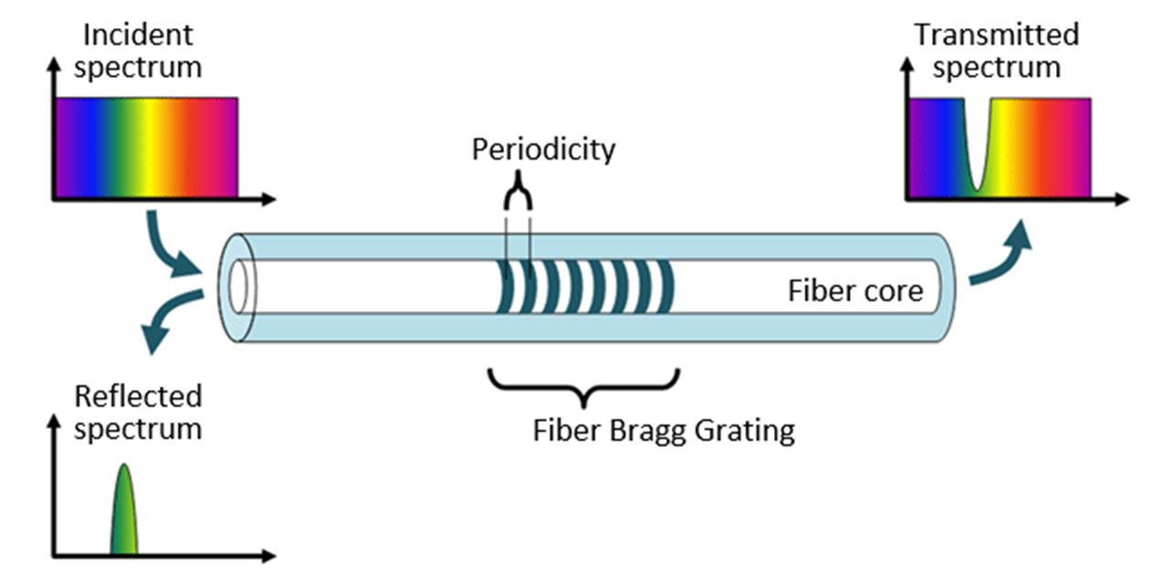
To reduce the emission bandwidth and improve the overall laser diode stability, laser diode manufacturers often add a fiber Bragg grating within the output fiber.
A Bragg grating adds a few percent reflectivity to the laser diode at a very precise wavelength. This allows the overall reduction of the laser diode emission bandwidth. The emission bandwidth is typically 3-5 nm without any Bragg grating, whereas it is much narrower (~< 0.1nm) with a Bragg grating. The wavelength spectrum temperature tuning coefficient is typically 0.35 nm/°C without any Bragg grating, whereas it is much less with a Bragg grating.
The major suppliers for 915/976/1064 nm single mode pump laser diodes are companies which developed their businesses at the end of the nineties for fiber amplifiers used in the Telecom market (EDFAs: Erbium Doped Fiber Amplifiers). They offer both a high level of reliability and a moderate cost due to their high production volumes.
b) DBR or DFB laser diodes
DBR or DFB laser diode devices have the Bragg grating wavelength stabilization section directly integrated onto the laser diode chip section. This provides a narrower emission wavelength of typically 1 MHz for a DFB (i.e. ~10-5nm) instead of ~0.1 nm for a Fabry-Perrot with Bragg grating.
Figure 8 : Principle of a DFB and a DBR laser diode (courtesy of Remi Arieli : “the laser adventure”)
Figure 9: Example of a 180 mW DFB laser diode seeder @ 1310 nm from AeroDIODE
c) Pulsed properties / Gain switching
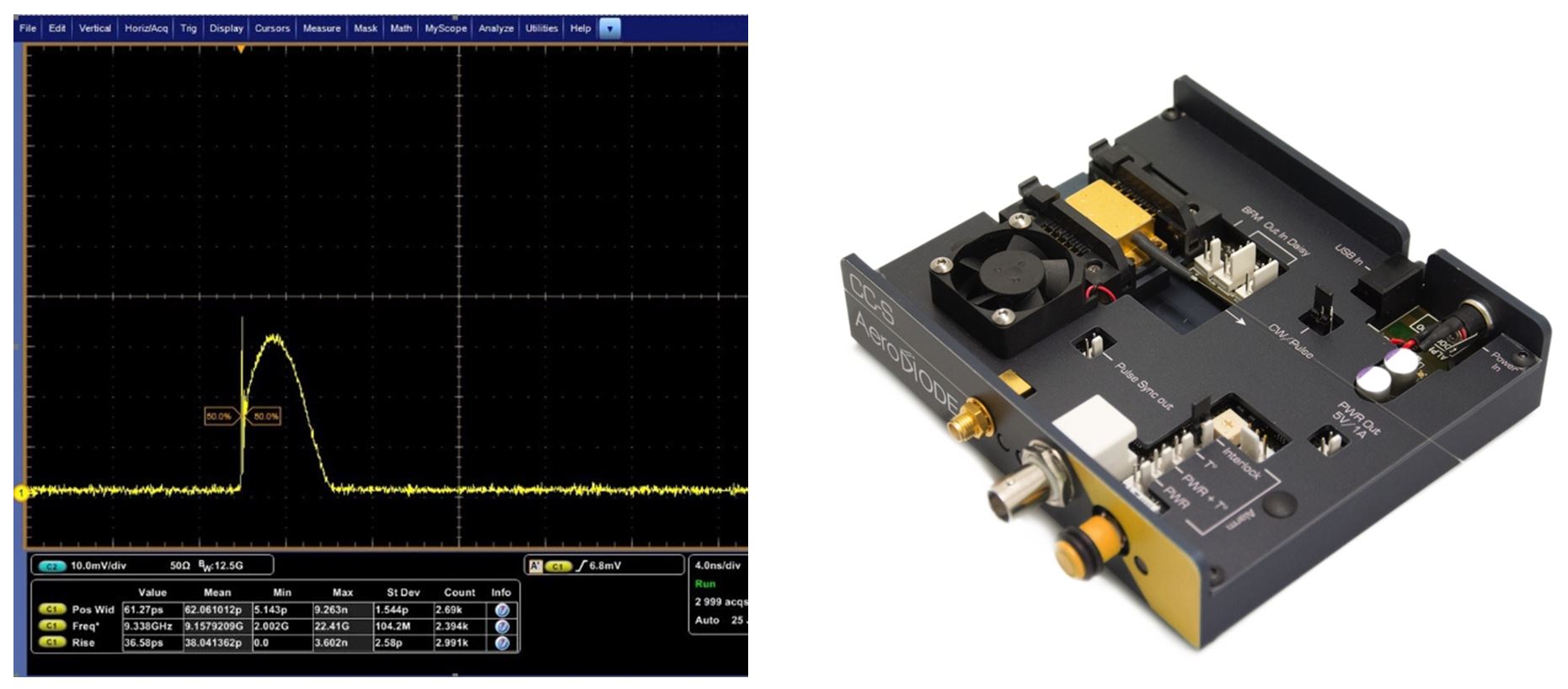
A simple solution for modulating the light coming in from a fiber-coupled laser diode is to apply a direct modulation using a pulse control electronics current driver. An example of a 3-nanosecond pulse width is shown below. One can see the gain switch peak at the beginning of the pulse. This is a relaxation of the carrier within the laser diode. Gain switch peaks can be useful if one wants to isolate this gain switch peak pulse and get ~ 100 picosecond pulses. But the gain switch peak is typically an undesired property (see below).
There are few companies around the world who specialize in manufacturing commercially available laser diode pulse drivers. However, the pulse shape at a short pulse width and the rise/fall time and Jitter levels can differ greatly from manufacturer to manufacturer. Also, there are many key features and additional functions which vary between manufacturers. Ease of use is also to be considered.
The bandwidth limitations are a result of the speed of the electronics on the “drive side” and the inductance of the laser diode on the alternant side. Reaching a 5 nanosecond per amp rise/fall time is possible in an ON/OFF switching mode from many suppliers. However, combining modularity, ease of use and high-performance levels is the most difficult part when developing a pulsed driver.
AeroDIODE offers several ON/OFF laser diodes switching driver models with switching speed from 3 nsec/A to less than 0.5 nsec/A.
Another high-performance product for direct laser diode modulation is called a “Pulse-Shaper”. It includes an internal AWG (Arbitrary Waveform Generator) and can shape the laser diode output with 48 dB amplitude resolution and 500 picoseconds of timing resolution. See this high speed laser diode driver.
Figure 10 : 3ns stable pulse width from the direct pulsing of a DFB Butterfly laser diode with AeroDIODE pulsed laser diode driver.
Figure 11 : AeroDIODE shaper module set in direct driver configuration (left) and special optical pulse shape obtained from a DFB laser diode after its programmed within the module (right)
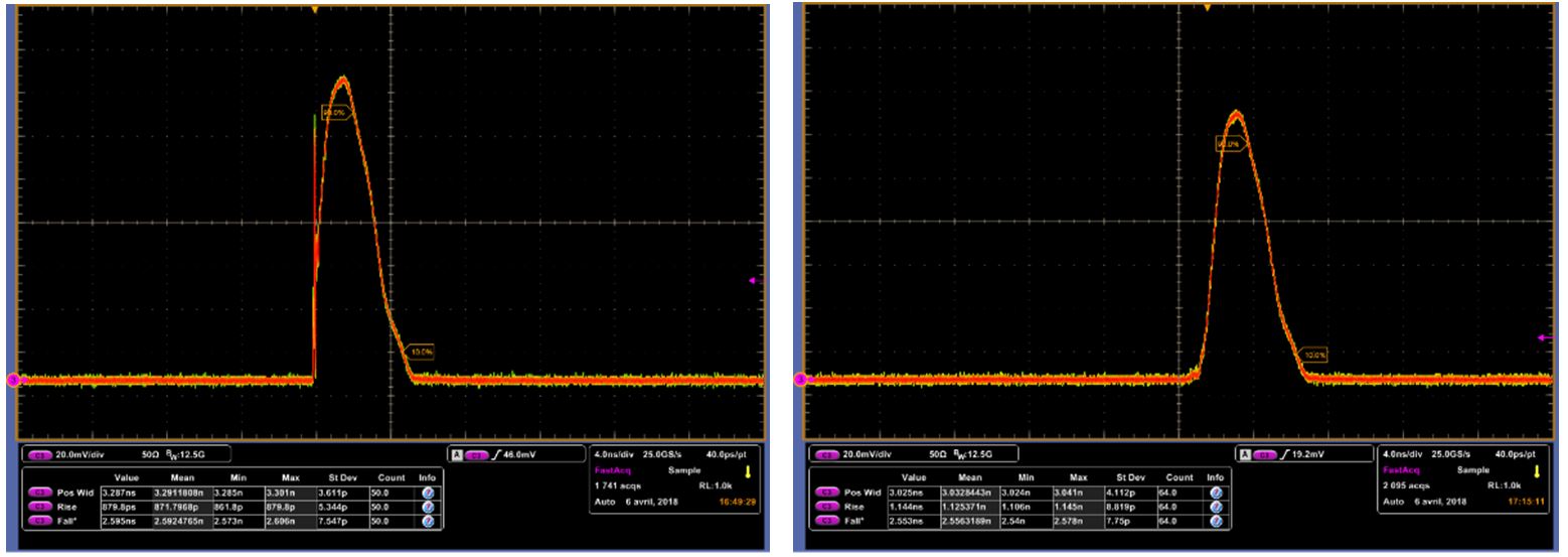
This pulse-shaper module allows the user to program a customized shape with a high bandwidth AWG and generates the desired custom optical pulse shape. As seen in the figure below, this module also has a special internal function which allows the user to mitigate the gain switch peak:
Figure 12 : 3ns pulse shapes out of a DFB laser diode driven by AeroDIODE shaper modules. The left curve has a gain switch peak which is suppressed on the pulse on the right by activating the internal “gain switch peak suppression” function.
d) Spectral properties
When considering the evolution of the emission spectrum of pulsed laser diodes, the user should understand two undesirable spectral effects:
The first is correlated to the time required for the laser diode to “lock” onto its Bragg locking element. This locking is immediate for a DFB but often requires more than 100 nanoseconds for a Bragg grating based laser diode. In other words, when pulsing Grating stabilized laser diodes, the first nanosecond produces a broad emission spectrum as if there was no Bragg grating. Some suppliers offer an intermediate solution called “Bragg close to the chip” which takes only a few nanoseconds to lock.
Another unavoidable effect comes from coupling of the frequency/phase spectrum and intensity profile. More specifically, the emission spectrum can change over the pulse length and this can sometimes be a problem. External modulation with, for example, an SOA offers a smart solution to avoid this effect. See our Tutorial: High speed fiber modulator basicsfor a detailed comparison of the four commonly used technologies for modulating laser light externally.
Table 1 below provides an overview of these spectrum evolution effects – with either the temperature or the level of current – depending on the laser diode technologies (DFB laser diode or Fabry-Perrot laser diode) :
Table 1 : Comparison of Fabry-Perrot and DFB-based laser diode spectral evolution:
Peak Wavelength evolution…
Fabry-Perrot
DFB
With Temperature
~ 0.35 nm/°C
~ 0.06 nm/°C
With the level of current
~ 5 nm/A
~ 1 nm/A
The spectral evolution of the Fabry-Perrot emitting chip is thus typically 0.35 nm/°C and 5 nm/A. Note that the Bragg Grating locking achieves good spectral stability when its own narrow peak wavelength is comprised within a wavelength range of the chip peak emission wavelength ± 5 nm.
It is interesting to note that the spectral properties of a Fabry-Perrot laser diode driven in pulse regime shows an evolution in the first 100s ns. The graph below shows some measured curves of such bandwidths.
Figure 13 : Emission bandwidth evolution of a Fabry-Perrot laser diode with Bragg Grating. The laser diode emission behaves as if there was no Bragg Grating for very short pulses.
The spectral bandwidth of a DFB laser diode is thus much narrower in CW regime than a Fabry-Perrot laser, even with a Bragg grating.
DFBs also show some evolution of the emission wavelength with both the temperature and level of current. These are much less than Fabry Perrot technologies and are compared below.
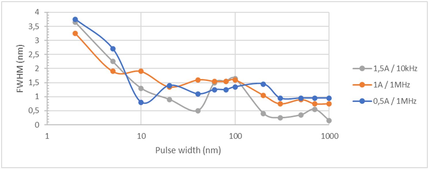
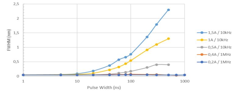
It is also interesting to look at the emission bandwidth evolution when considering short pulses. We can notice that the emission bandwidth stays narrow when considering short pulse only when the level of current stays below 200 mA (OSA minimum resolution of 0.04 nm here is observed for 0.2 A pulses). However, we start observing a significant bandwidth evolution when considering higher peak current.
Figure 14 : Evolution of the bandwidth of a DFB laser diode when driven in pulse regime – Bandwidth can become very broad when driven at high current level.
e) Driving a singlemode laser diode
Driving a singlemode laser diode in CW or pulse regime is a difficult task which requires specialized products. Here are three laser diode drivers which have been specially designed for both R&D and full photonics system integration. All these drivers include a TEC control part which allow the user to adjust the laser diode temperature.
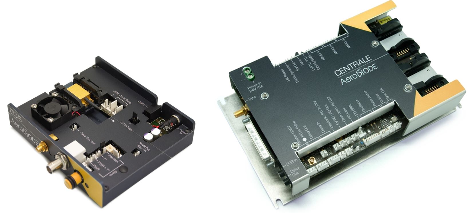
The CCS from AeroDIODE is a pulsed & CW laser diode driver with TEC control. This pulsed laser diode driver delivers precision pulses which are generated internally by an on-board pulse generator, or on-demand from an external TTL signal. It is compatible with most of the available single mode laser diode form factors. Butterfly laser diodes are easily driven in CW or pulsed regime at any frequency and any duty cycle up to 250 MHz repetition rate. Refer to this product page : pulsed laser diode driver
The Central board from AeroDIODE has one laser diode channel optimized for low noise CW driving and one channel optimized for both CW and nanosecond short pulsing. It also contains many fiber laser relevant functions, such as multiple photodiode inputs. The central board can act as a “control center” for a fiber laser. Central boards have more than 50 high tech functionalities optimized to build and integrate a fiber laser. Refer to this product page: fiber laser diode driver.
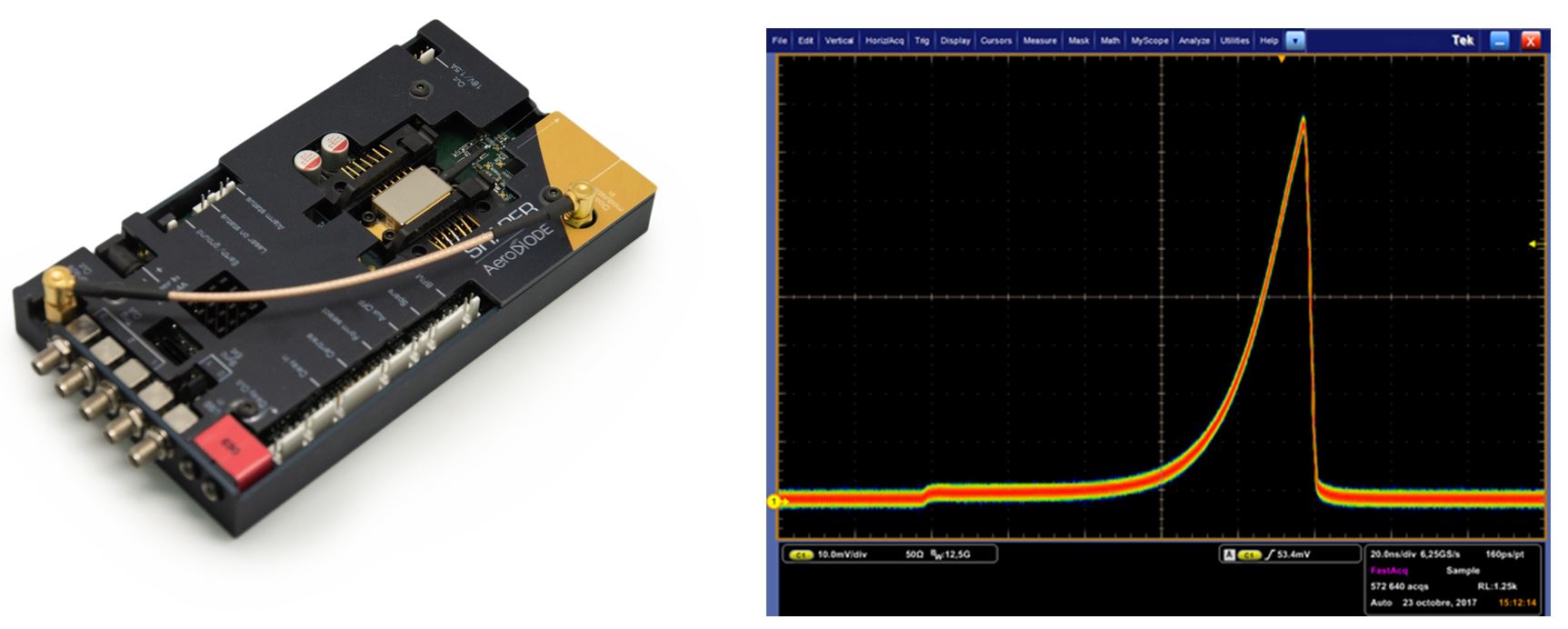
The Shaper board is another driver offered by AeroDIODE that can solve many issues detailed in the sections above: it can pre-compensate the pulse shape and has a special Gain-Switch suppression function. The shape can be adjusted down to very short pulse widths because its internal AWG (Arbitrary Waveform Generator) generates one point every 500 ps with 48 dB dynamic range. It also contains 3 pulse delay generator outputs. See this product page: high speed laser diode driver.
Figure 15: AeroDIODE optimized laser diode drivers: CCS is a universal Pulsed laser diode driver generating pulses from 1 ns up to CW signal (left). Centrale board is multi-channel fiber laser diode driver optimized for single mode laser diodes with many fiber laser optimized functions (right)
Figure 16: AeroDIODE shaper module (left) is a high speed laser diode driver which generates specialized optical pulse shapes. For example, a pulse obtained from a DFB laser diode after it has been programmed within the module (right)
Multimode fiber-coupled laser diodes
a) The 4 families of multimode fiber-coupled laser diodes
Multimode fiber coupled laser diodes are based on broad area side emitting laser diode chips initially designed and made from a semiconductor wafer.
There are 4 types of Multimode fiber coupled laser diodes (see Figure 18 and Figure 19):
Single emitters: when a laser diode chip is isolated, assembled on a sub-mount and packaged alone in a laser diode module. We talk here typically about 15W of power coupled into a 105 (core)/125µm(clad) laser diode
Multi emitters: when several emitters are separated and optically coupled together with other isolated emitters in a multimode fiber (Figure 19-right). The level of output power is thus scalable up to several hundred watts and the size of the fiber can be kept small like 100 or 200 µm core.
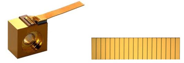
Single bars: when several emitters are kept together as a single bar (Figure 17) and assembled in a laser diode module. We talk here typically about 50 W of power coupled into typically a 200 µm(core)/240 µm(clad) laser diode
Multiple bars: When several bars are assembled in a large water-cooled package and coupled in a large diameter multimode fiber. We talk here about 100’s of W of even KW coupled into, for example, 600 or 800 µm core multimode fibers.
Figure 17 : Example of laser diode elements – single elements assembled on a sub-mount (left) or a single bars made of 19 emitters. (courtesy of Innolume and Seminex)
All these laser diodes have very different packaging:
Figure 18: Example of multimode fiber coupled laser diode modules : (left: multi-emitter 35W laser diode ; middle: single-emitter 10W @ 915 nm from AeroDIODE ; right: various laser diode single and multiple bar-based sources from DILAS (Courtesy of AeroDIODE and Dilas - now Coherent )
It is interesting to notice how the typical voltage and current levels change when considering the various families:
A typical unitary emitter has a typical voltage level of ~1.5 V and a current of ~15 A.
For a multi-emitter laser diode, the emitters are assembled in series. It means that the level of current does not change (typically 15 A max), but it is the voltage which increases when considering more and more emitters. (for example, 4.5V/15A for a 60 W laser diode)
A laser diode bar assembles all the emitters in parallel. So, the level of voltage does not change, but the level of current can easily reach 45 or 50 A.
Again, when assembling several bars together, these are assembled in series, so the level of current (for example 45 A) does not change, but the voltage increases regularly with the number of bars.
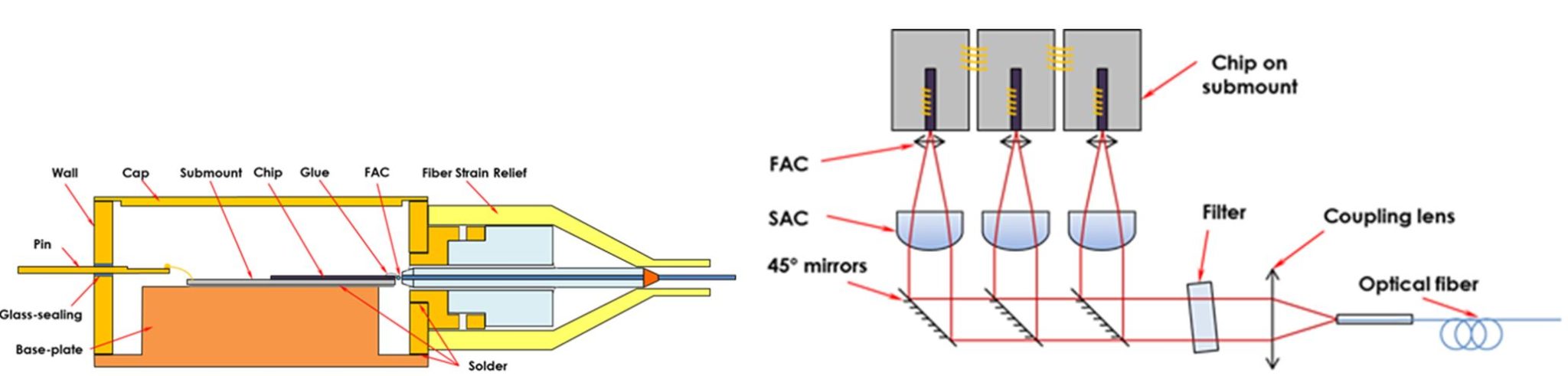
b) Construction and form factors
Figure 19 shows some examples of the construction of a single element and multiple element laser diode. One can see that separating several laser diode elements and combining their laser light into a single fiber allows the increase of the power/surface at the fiber. On the other hand, a laser diode bar is strongly asymmetric and makes it more difficult to inject light in a circular fiber. This makes the minimum fiber diameter of a laser bar technology generally larger than for a multi-element technology.
Figure 19 : Example of construction of a single element laser diode (left) and multiple (3)-element laser diode (right)
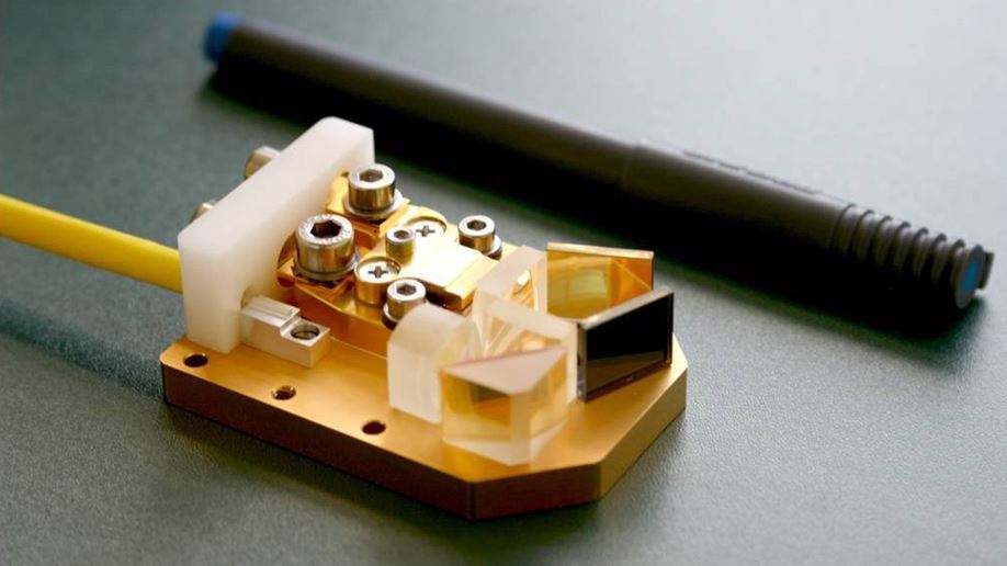
Figure 20 : Example of a laser diode bar fiber injection setup. (Courtesy of Fraunhofer IOF)
c) Spectral properties
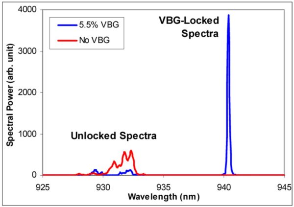
Note that many applications such as the pumping of rare-earth ion like Yb3+ at 976 nm require a stabilized and narrow laser diode emission spectrum. This wavelength stability requires the laser diode temperature to be controlled and often the laser diode to include an additional wavelength stabilizing element. This element is generally a VBG (Volume Bragg Grating) for multimode laser diodes. The VBG is a specialized piece of glass integrated into the laser diode package.
Figure 21 : 940 nm VBG locked spectra of a 930 nm emitting laser diode (Y.Li et al.)
d) Driving a multimode laser diode
Driving a Multimode laser diode is a difficult task which requires specialized products. Especially when considering >10W output power laser diodes, the thermal cooling becomes a real subject. Here is a laser diode driver which has been specially designed for fiber laser diode driving and are compatible with both R&D and full fiber laser product integration.
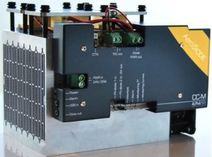
The CCM (Cool and Control Multimode) from AeroDIODE (see this page : high power laser diode driver) is fully optimized for driving one or several multimode pump laser diodes (either single element or multiple element devices). It is provided with a TE-Cooler which allows to adjust the laser diode temperature. It is an air-cooled device compatible with laser diodes up to 200 W optical power.DIODE
Figure 22: AeroDIODE high power laser diode driver. Ideal for multi element laser diodes like II-VI, Lumentum, IPG etc.
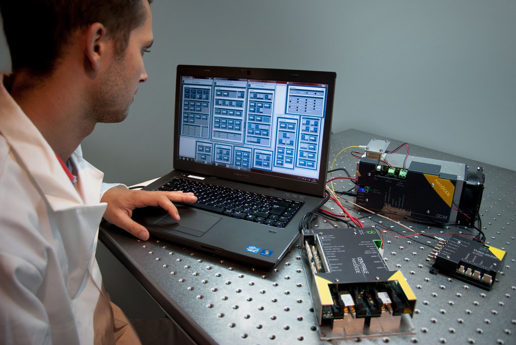
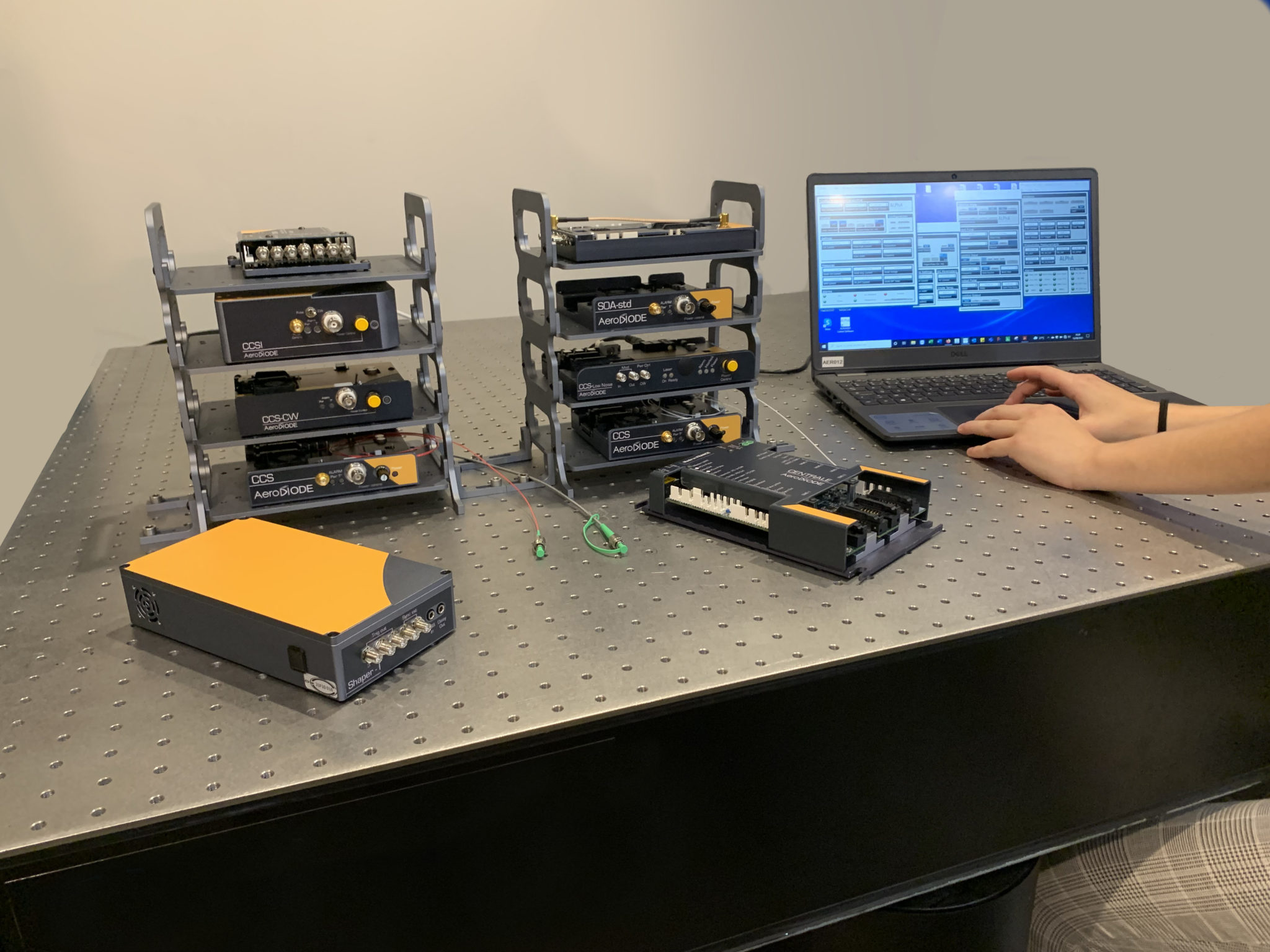
A modular laser electronics family compatible with nearly any type of photonics system
AeroDIODE has developed an entire range of electronic drivers able to build nearly any type of laser diode-based photonics system. These drivers can communicate together and can control any type of laser diodes in either pulsed or CW regime. They are designed to make it simple to integrate them into a compact prototype. This allows for a much faster photonics system development time frame for the designer.